From Arcs to Motion -
Understanding the Signal Story
Turn Calibration - How the Curves Become Headings
How satellite timing, Doppler shift, and turn dynamics transform arcs into a measurable flight path
Curved paths in satellite-based reconstructions are often treated as visual approximations—smooth arcs connecting uncertain positions.
In this framework, curves are not drawings.
They are measurable results of aircraft motion.
Turn Calibration is the process of translating those curves into:
- Defined heading changes
- Measurable turn rates
- Time-aligned motion behavior
This transforms a visual path into a physics-based reconstruction driven by the signal itself.
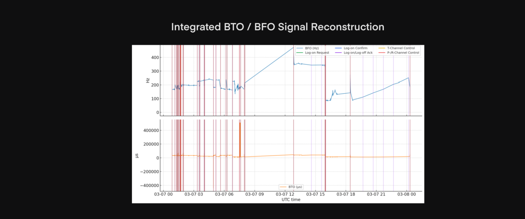
Satellite data does not directly show a flight path — it shows signals.
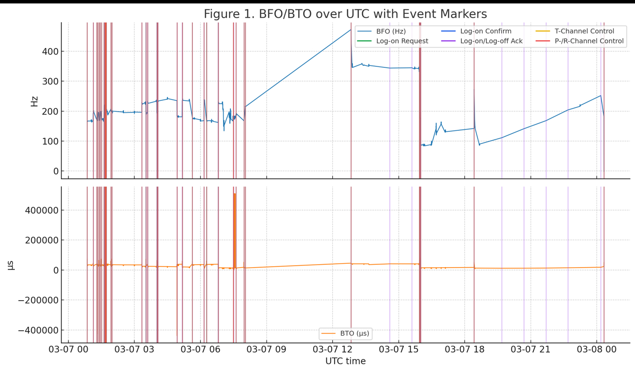
- BTO (Burst Timing Offset) measures distance from the satellite
- BFO (Burst Frequency Offset) measures motion through Doppler shift
- Signal Sequencing converts isolated handshakes into continuous behavior
The Etch-a-Sketch Model transforms these signals into motion — one step at a time.
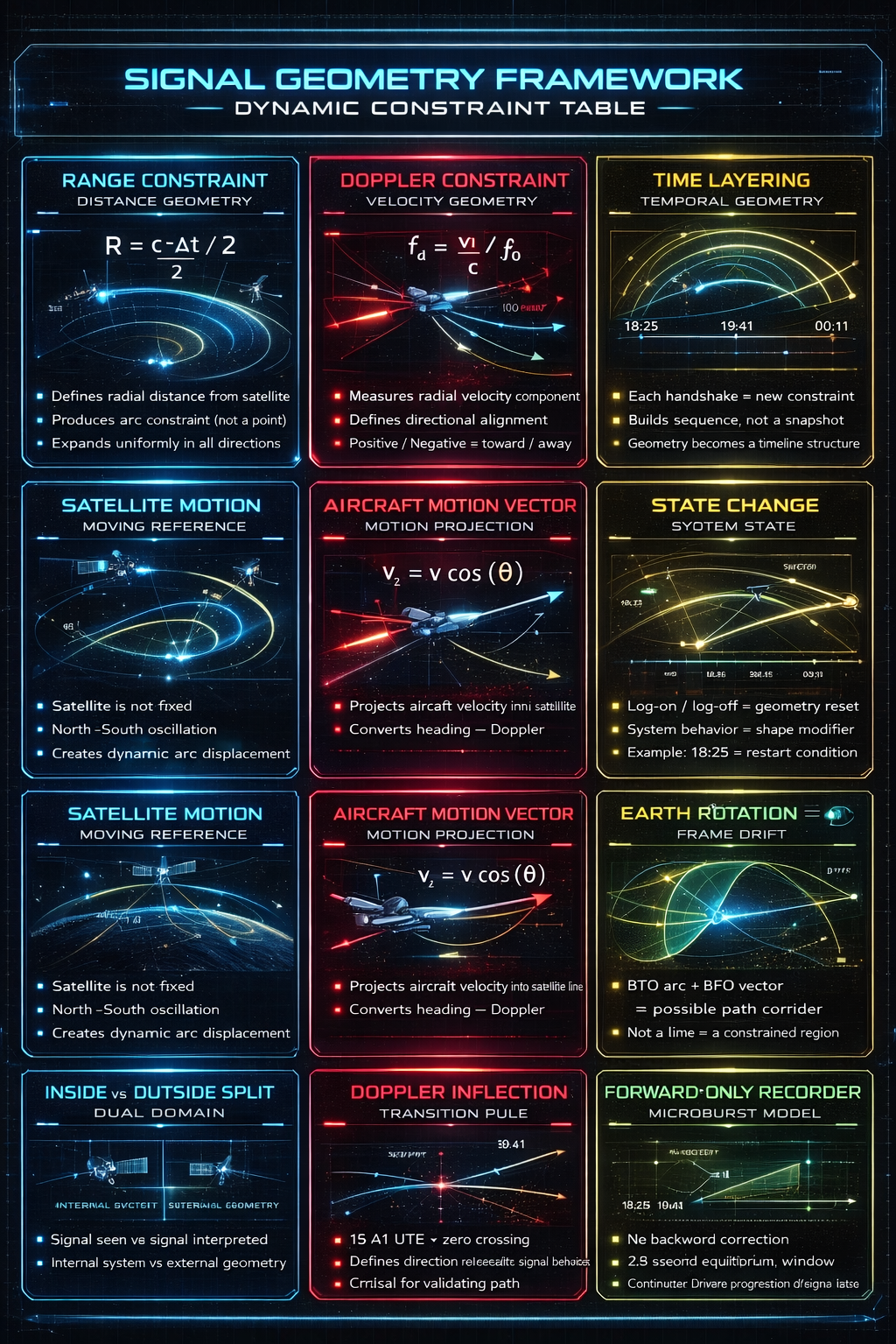
SIGNAL GEOMETRY FRAMEWORK
Understanding the Signal Geometry Framework
This framework organizes how satellite signal data is used to reconstruct aircraft motion.
Rather than treating each measurement separately, the system combines distance, motion, time, and system behaviorinto a single structured model.
🛰️ What You’re Looking At
Each panel represents a core component of the signal:
- Range (BTO) defines how far the aircraft is from the satellite
- Doppler (BFO) reveals how the aircraft is moving relative to it
- Time sequencing connects each measurement into a continuous timeline
- System state reflects how onboard systems influence the signal
Individually, these elements provide partial information.
Together, they form a set of constraints that limit where the aircraft can be and how it is moving.
⚙️ How the System Works
The model does not assume a flight path.
Instead, it builds one by:
- Applying distance constraints from timing
- Applying motion constraints from Doppler
- Aligning both across time
- Incorporating system events as physical markers
This process transforms signal behavior into a measurable trajectory.
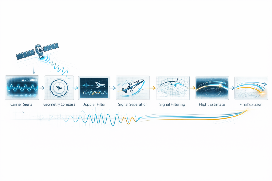
From Signals to Motion: The Etch-a-Sketch Reconstruction
From Arcs to Trajectory
Traditional interpretations rely on arcs and isolated measurements.
This method goes further — combining timing, frequency, and sequence into a unified motion model.
Instead of asking “Where could the aircraft be?”
we ask:
“Where must the aircraft go next based on the last signal?”
This forward-only constraint eliminates impossible paths and reveals a consistent trajectory.
Step-Based Signal Reconstructionn
Each satellite handshake is not a path — it is a single data point.
The aircraft’s trajectory is revealed only when these points are connected in sequence.
Using a step-based method:
- Each BTO defines a position constraint
- Each BFO defines a directional movement
- Each timestamp locks the sequence in time
The Etch-a-Sketch approach connects these steps forward only — never backward — producing a continuous, physics-based flight path.